

Last article What is SWR and … I mentioned that some watt-meters are basically voltmeters calibrated in watts and that we’ll talk about it a little more sometime next time. That next time came now, so I’m going to try to write something about it. I would add at the outset that I want to mention the things needed for practical use so that we do not describe in detail the vectors of performance, mathematical solutions, etc. who cares will certainly find articles on the Internet that deal with this issue in detail and describe the theory really comprehensively. However, we will try a practical demonstration which is important to us from the point of view of radio amateurs, but we cannot do without basic concepts.
How we measure electrical power
In electrical engineering, we measure power directly with a watt-meter or voltmeter and an ampere meter, and we can calculate the power based on these measurements. For easier understanding, let’s start in DC circuits where power is defined as the product of voltage and current.
P=U.I
- P – is the power in Watts [W]
- U – is the voltage in Volts [V]
- I – is the current in amperes [A]
It’s a very simple relationship where it’s clear at first sight that we need to measure both voltage and current to determine performance. Measuring instruments that measure our output directly must therefore have two measuring inputs, namely voltage and current. If we do not have a Watt-meter, we will be sufficient with the amp-meter and the voltmeter and simply multiply the measured values.
However, this applies to the DC system. So if we want to measure power in AC, we are getting into a more difficult situation because a phase shift between voltage and current will get in the way of what we call a power factor called cos Φ. This phenomenon will complicate the situation by the fact that instead of one power, we will see 3 powers, which we have named:
- Active power which is defined as : U.I.cos Φ
- Reactive power which is defined as : U.I.sin Φ
- Apparent power which is defined as : U.I
If we try to install the angle of the phase feed current and voltage 0 we find that:
- Cos 0 = 1
- Sin 0 = 0
Once added to the previous formula, the reactive power disappears and the active will, as well as the apparent one, be defined only by the product of voltage and current, i.e.:
P=U.I
In doing so, we elegantly got rid of the long description of what this powers means, and again we have only one simple relationship, as in the case of the DC system. All we have to do is phase shift between voltage and current 0 degrees. What this means to us and how we will comply with this condition in case of measurement of RF power, we will say a little later.
Measurement of RF power
Radio amateurs are usually interested in RF power. Whether it’s transceiver power or RF amplifier, it’s alternating performance. If we ensure a phase shift between the current and a voltage of 0 degrees, we can use the relationship:
P=U.I
In order to meet the condition of phase shift 0, we must ensure that the measurement takes place under a purely resistant load, i.e. that the load will have neither a capaciting nor an inducive component. The easiest way is to use an dummy non-induction load. However, if we use an dummy load whose parameters will be constant throughout the measurement, we can make it even easier.
Ohm’s law without which we simply can not do
Ohm’s law will help us simplify because it talks about the relationship of voltage, current and resistance.
I = U/R
Since the dummy load will have a constant resistance value we can afford to use this fact and install it in the previous formula P=U.I instead of the current from ohm’s U/R law. We will create an elegant formula where the current disappears and only voltage and resistance remain in it :
P = U.U/R
P = U2/R
Since we know the resistance of the dummy load, we only have to measure the voltage, i.e. that the watt-meter for RF power is basically voltmeters calibrated in watts.
Things to watch out for
Since the calibration of such a watt-meter depends on the resistance of the dummy load, we must remember that in the case of resistance other than 50 j0 (ohms pure resistance) such a watt-meter will no longer show us the correct values. This is due to the fact that since it is basically a voltmeter it measures the voltage which, under a different load, already corresponds to a different power from the 50 ohm on which it was calibrated. Power should therefore be measured in dummy load and not in the antenna. If we measure the power to the antenna, we can only believe its data if the antenna on a given SWR frequency is close to 1:1, this fact is often forgotten, and then when measured into the antenna, we get senseless power values that can in some cases be dramatically different from reality.
Let’s imagine a situation where we measure 100W of power. This power corresponds to a voltage at 50 ohm load of about 71 Vrms. At this voltage value, the watt-meter per 100W is calibrated. However, if we measure into an antenna with an impedance is etc 25j0 (where SWR is 2:1), the watt-meter measures a voltage of 50 Vrms, but at 50j0 the load voltage of 50 Vrms corresponds to a power of 50W i.e. the watt-meter will show a measured value of 50W instead of 100W. However, this is true for very simple watt-meters that we can still encounter in practice, but of course there are other more sophisticated types.
Not a watt-meter like a watt-meter
In practice, we can encounter types of watt-meters that actually measure only the voltage and the power is recalculated due to the constant 50 ohm load. Their construction is usually very simple and is used more for CB bands or for the HF. One such type is also the SWR meter and Watt-meter ALAN K155.
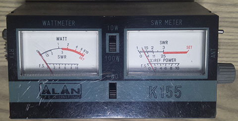
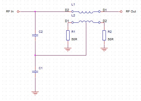
Power measurement is structurally designed really very simply and not very well. A capacited voltage divider is connected directly to the input. From its center, a signal is brought to the hand gauge via a RF detector and filter. It’s basically a RF millivolt meter, calibrated in watts. This is sufficient for measuring into dummy load, but if we were to measure the results directly into the antenna, the results would be highly dependent on the antenna being tuned.
However, let us return to the original relationship for calculating performance, not :
P = U.I
With less load impedance, we have a smaller voltage, but the current must be increased to keep the power the same. I.e. if we were to introduce dependence on the flowing current in the measurement, we could measure performance with relatively sufficient accuracy even on an antenna that is not ideally tuned. For such measurements, connections which measure both current and voltage are used and the sum of the two measured voltages (because even when measuring the current is the result of some voltage) the inflow of the meter is controlled which, although again voltmeter, is already compensated for by the voltage and current dependence on the measurement. In practice, two basic connections are mainly used. And that involvement with the so-called Bruene directional coupler, where a current transformer is used to measure current, which is voltage-offset by the output from the capacitor voltage divider.
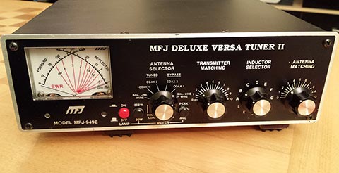
It is an older wiring from the 1950s but is popularly used in many watt-meters e.g. in MFJ949 tuners where it is slightly modified but basically the same.
Another connection used is called Tandem – Match. It is very similar to the topology as in the previous case, but the capacity divider is not used to inject the voltage level, but the voltage coil of the tandem transformer.
Conclusion
As you can see involved are a few and not everyone behaves the same way. If we’re not sure what kind of watt-meter we’re supposed to measure up to dummy load and not rely on the data we’re measuring into the antenna. However, if we have a watt-meter designed as in the last two demonstrations, it is possible to measure power with it also to non ideally tuned antenna, but the compensation members of the current and voltage do not compensate for everything that happens in the case of a not well-tuned antenna, so I recommend always using the non-induction dummy load and measuring the antenna only as an informative value that may be more or less different from reality. However, one essential thing to be aware of, and that is the fact that when measuring voltmeter power (which are basically all , the voltage in the square is that the power grows with a square of voltage.
P = U2/R
Translated into human speech, this means that even a small change in voltage will make a big change in power, i.e. that the already small inaccuracy in the calibration of the watt-meter indicator, which is basically a voltmeter, will make us a great inaccuracy in measuring power. There is also considerable non-linearity with respect to the measured frequency, so broadband watt-meters without some sophisticated compensation controlled by the microprocessor will not be very accurate (that is why the American company Bird produces such a wide range of Bird elements). Simply any analog watt-meter whose bandwidth will be too large cannot be measured accurately at all frequencies. If you have a choice between multiple Watt-Meter bands with narrow switchable ranges, then there is a greater likelihood that such a watt-meter will be measured more accurately because there is a chance of much better compensation for inaccuracies due to the greater number of ranges. Therefore, even measured results with conventional watt-meters should be taken with reserve. I dare say that the 10% deviation from the maximum measured range is still relatively fine.