

What is RF generator
The RF generator is one of the basic instruments for any radio amateur who wants to measure, adjust, construct or experiment in the area of RF. It is good to detect some problems in the RX part of the transceiver, measure and adjust sensitivity or if you own more TRXs you can find which receiver is more sensitive and much more. The RF generator for the RX part of the transceiver is something like an dummy load for its TX part. It’s a signal source that has a constant level regardless of the conditions of spread outside the hamshack. Just as we can’t imagine setting the TX part of the TRX (measuring power, measuring higher harmonics or adjusting modulation circuits) without dummy load, an equally important help for us is the RF generator. It’s an indispensable helper in setting up every transceiver and with a little imagination with it we can do a lot more than it might seem at first glance.
Where did I get it ?
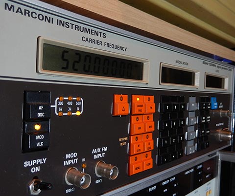
Since measuring instruments for RF technology are quite expensive so radio amateurs who do not want to use them for commercial purposes, have nothing left but to look for older spoiled devices and get them repaired as far as possible. Some time ago, in one internet auction I won RF generator Marconi 2018A. Although the auction said it was broken and the photo was taken with a failure message of missing 10MHz references, the image shows that EXT is set as the reference source, which means that it is necessary to bring a 10MHz sine signal to the BNC connector on the back of the device otherwise the device will write out this malfunction. After I switched it on for the first time, I changed the reference signal source to INT, which means its internal TCXO will be used and the malfunction has disappeared. I didn’t want to believe that someone would sell it for such a triviral thing, but since it is a device that is now unsuitable for professional purposes in terms of low maximum frequency range (which the vast majority of radio amateurs would do lavishly enough) I thought it might be uninteresting for the person in question. So after the first switch-on, he looked flawless, but it wasn’t until after a while that I noticed some anomials. I’ll say I didn’t figure it out right away, and I thought it was fully functional for a while. Since it was one of my first RF measuring instruments at the time, there were not many options to test it in detail at the time, and I only found out the real reason for the sale later when I got a spectral analyser. First, however, let us talk about the basic technical parameters of this device.
A few technical data
RF generator Marconi 2018 can operate in the range of frequencies 80kHz to 520MHz and the output level can be set in the range of -127dbm to +13dbm. The output signal can be modulated by AM, FM and Phase, and the tone of the modulation generator can be set in 6 steps (300Hz 400Hz 500Hz 1kHz 3kHz and 6kHz) and also can be modulated from an external source. RF output is adapted to impedance of 50 ohm. The RF generator is equipped with an internal TCXO but can also be synchronized from an external 10MHz reference signal source. In the device settings it is possible to preset in which units to display the output level which is especially advantageous when adjusting transceivers where the manufacturer once indicates dBm other times dBuV or the voltage level in uV or mV (which is advantageous in measuring the sensitivity of the receivers). It is also possible to set whether it will be e.m.f. or p.d. so if you set the output level e.g. in dBuV units don’t forget to check what reference level the manufacturer had for 0 dBuV in mind (older Yaesu devices have in the service manuals indicated that 0 dBuV is 0.5 uV and you can just set it by setting the aforementioned e.m.f. or p.d. This will reduce the long recalculation and make it much easier to work with the device.
So where was the problem?
When I got the spectral analyser that I noticed one thing that once the output level is a few dB less than ever. In case I entered it directly from the keyboard was mostly the same but the problem arose mainly when dealing with the UP and DOWN buttons, so that if I was to step to any level required from the lower value ie. that I gradually added the UP button so that when the desired level was reached, its value was different from the fact that I had reached it from a higher level by pressing down. However, this was not the case with every output level value, but only for some. However, this phenomenon was repeatable, so if I repeated it on the value on which it happened it always happened. Thus, it was not bad soldering or oxidation on the contacts of the relay or something similar. I tried to find some logic in it and so I went through the entire band of output levels from -127 dBm to +13 dBm in steps +-1dBm and I found an interesting thing. Iall the output levels range there were several windows in which the device did not react and the output level remained unchanged several dB. However, there was an interesting phenomenon, and that if for example I step up so that in the event of a hit on such a deaf window (e.g. the output level did not respond during three steps) but after pressing the button down suddenly changed to the correct value. (this was similarly behaved in the case of top-down negotiations). I’ve noticed that the level change has gotten to normal after an acoustic click of a relay. These windows were repeated every 10dB. These observations have shown that it probably has something to do with this coarse attenuator, which is made up of several relays and can be anated in just the +-10dB steps. Marconi 2018 but has 2 attenuators and it is fine and coarse. Fine attenuation is done electronically and can cover anything more than 10dB (I don’t remember exactly yet but I feel like 16dB. The coarse attenuator is formed by several relays and its smallest step is mentioned 10dB. By combining coarse and fine attenuator, any output level can be reached between -127dBm and +13dBm in very fine resolution. The combination of a coarse attenuators relays and an electronic attenuator controls a microprocessor that uses an algorithm to prevent frequent click-in relays, using an algorithm that uses the fine attenuator to have a larger frame than the step of the coarse attenuator (i.e. more than 10dB) and therefore click the coarse attenuator revisor at values other than in the downward process. The last interesting finding was that the RF generator cannot reach a higher output level than +4 dBm so that in the last attenuating step of the coarse attenuator where it does not actually adlate because it is switched to position 0dB is the mentioned phenomenon not in width 6dB but to 9dB (13dBm – 4dBm). So I’ve ruled out a coarse attenuator and I’ve started to deal with a fine attenuator that’s not made up of retiners but is electronic. After studying the schemes, I found that it was not so much an attenuator but rather a sophisticated wide-band amplifier whose gain is controlled by a microprocessor, and regulation is provided by feedback from its output thereby being compensated for both thermal and amplification losses, whether output transistors or other elements due to for example aging etc. I have found that the entry into the whole complex of amplifiers and modulators that this part is made up of is in order in all steps, but the output already shows the anomals mentioned above. After a more detailed measurement, I began to suspect the TR1 transistor in the AC5 (amplitude modulator) which, although we do not want to modulate the signal, is involved in the complex process of the signal path and it was on it that the measurements found that the anomaly begins here. If this transistor had lost its amplification, the plot would have been similar to what I had found by the measurements, namely that the required output level would still be in line with that, but once the maximum intervention has been reached, the size of the output signal will no longer increase, which would explain the max output level of +4 dBm and also the above-mentioned deaf windows in the other parts of the required levels. I replaced this transistor, but the problem was still there. The TR1 transistor is drived by double-balanced X2 mixer that I firmly hoped would be OK. This mixer is drived by a VF amplifier IC1 hybrid integrated circuit case labeled OM345. This circuit did not work properly and did not achieve the amplification as it should have achieved. The good news is the datasheet wasn’t a problem to get hold of him, but the bad news was that it’s no longer manufactured and it’s a problem to get hold of.
How I solved the problem
After searching the Internet, I learned that this circuit was popularly used by Marconi Instruments in other of its products and that quite often it was a source of problems. However, I came across an article by clever radio amateur Miguel EA4EOZ, who subjected this circuit to a detailed examination and found that in most cases, one 3K9 resistor is interrupted in this hybrid circuit, but it is not easily replaced because this entire circuit is drenched in ceramic matter. Although the resistor is not brought directly to the OM345 hybrid circuit pins, by connecting the 4k7 resistor in parallel to pins 1 and 5, we will achieve a similar connection as in the original connection, however, since it is an alternative connection, it is possible that the circuit will not achieve exactly the same parameters as in the original connection. However, it is rich enough for the test, so I connected 4k7 resistor to pin 1 and 5. The circuit actually began to amplify as it should, and the generator reached the playful max output level of +13 dBm and the mentioned deaf windows at the other output levels actually disappeared. Miguel, however, went even further in his enviables and tried to remove the pottery from the hybrid circuit in places where the interrupted resistor is mentioned. Since I was a detailer I was not satisfied with the replacement solution and I also removed by gradually scraping the individual layers of ceramic matter the part described by Miguel until I got to the resistor. Since the ceramics hold really tight it was not easy, and even the mere soldering of the new 3k9 resistor was quite difficult (the ceramics on the original lifer left a kind of oxide on which it does not hold the tin well and needs to be thoroughly removed). I left the original ailed resistor in my place and solder on it in parallel new ones in smd package 0805. Experimental 4K7 resistor from pins 1 and 5 of course I removed. After testing the device worked as it should, but I don’t know if it would be a difference if I used an alternative 4k7 connection to Pins 1 and 5. Now, from hindsight I can see that it was quite risky because the whole hybrid circuit could have been damaged while removing part of the pottery and where i could get the other one I really don’t know. If you ever solve this problem I recommend alternative wiring of an external resistor 4k7 to pins 1 and 5 it is definitely safer and worth trying to leave in this connection.
If anyone would like to read the above article from Miguel EA4EOZ, then I get a link (at the time of writing this article was functional and accessible https://ea4eoz.blogspot.com/2017/09/repairing-om345-hybrid-module.html
Conclusion
The RF generator has been operational since this moment, but there are more OM345 on another boards so I am ready to possibility of another repairing but now I know how. At the end of the photo gallery there are a few photos of the dismantled device. It’s constructed by a sandwich type so that, both from the top and bottom, individual plates are folded through the gradual release. Groups of individual floors bear the designation AA AB AC followed by the plate number. The aforementioned OM345 circuit is located on the AC5 board which is located from the bottom of the device. The photos also capture the plates from the top, but in case you want to get directly to the AC5 board you do not have to disassemble the top but put the appliance upside down on the table and start disassembling the bottom. The photos indicated both the position of the AC5 plate and the direct circuit IC1 (OM345)
If I helped anyone with this article, I’m delighted. If you’d like to ask a question or share your experiences or if you have solved a similar problem write to the comments at the bottom of this article please.
Good luck and best regards
Igor OM4IK


great thanks for sharing it really helpful
hi there. I have a 2018a which has just failed. fault is no button indicator lights,display is there but you cant change it.08080000 ishown on display any ideas . regards mike. G3yad.
Hi Michael
It looks like program is halted (maybe memory problem or cpu problem). Check on board AA2 try to measure clock on CPU if there is some signal and frequency on 1 and 2 pin is XTal 6.144MHz (check with osciloscope). Then check clock on pin 37 of CPU and then clock on IC23 pin 8. You will need a schematic, try to find service manual its on the internet and look on page 203.
Good Luck
Igor
I have all the 2018A boards. If you need any I will send you my eBay store link.
The original 44828-440 PCB in working condition could be yours for only $40